Structural and Hydrodynamic Properties |
 
|
Structural and Hydrodynamic Properties |
|
Flexcom uses the concept of element sets to define the physical properties of the finite element model. Groups of similar elements are logically combined into named element sets, properties are then assigned on an element set-by-set basis. When lines are utilised during model creation, relevant element sets are created automatically, based on the names of each line (and subsection of each line if appropriate) in the model. From the line definitions detailed previously, the relevant element sets in this context are Outer Pipe, Inner Pipe, Oil Jumper, Gas Jumper, Lower Frame, Upper Frame, Buoyancy Tank, T-Frame-Leg and T-Frame-Top. Sets are also created for the Lower Flex Joint and the Upper Flex Joint, although the assignment of properties to these is slightly different to the other sets.
Flexcom provides two different formats for specifying structure geometric properties, although ultimately the information is the same and is used in the same way by the program. These are termed the Flexible Riser Format and the Rigid Riser Format. The Flexible Riser format is so called, naturally, because it is the format commonly used when defining flexible risers. Specifically, the data to be specified in this case comprises bending stiffnesses about two axes, torsional stiffness, axial stiffness, mass per unit length etc. When you use the Rigid Riser format on the other hand, you input internal and external diameters, Young’s modulus, shear modulus, mass density etc. – data for the analysis of a rigid riser (whether a top tensioned riser or an SCR) would normally be available in this format.
Both the inner and outer pipes are made of steel, and their structural properties are specified in the Rigid Riser format, as shown in the figure below. Refer to Geometric Properties in Rigid Riser Format for further information on this feature.
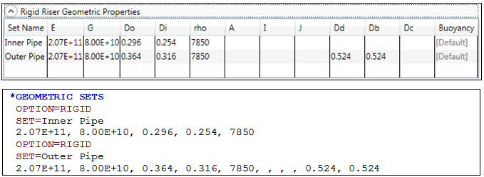
Structural Properties – Rigid Riser Format
Refer to the *GEOMETRIC SETS keyword for further information on these data inputs.
The outer pipe is also coated with insulation material, as shown in the figure below. Refer to Coatings for further information on this feature.
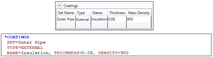
Application of Coatings
Refer to the *COATINGS keyword for further information on these data inputs.
Structural properties for the other element sets are specified in the Flexible Riser format, as shown in the figure below. Note that that symbol ![]() indicates that the following keyword data is supplementary to the existing data under the same keyword as shown previously. Refer to Geometric Properties in Flexible Riser Format for further information on this feature.
indicates that the following keyword data is supplementary to the existing data under the same keyword as shown previously. Refer to Geometric Properties in Flexible Riser Format for further information on this feature.
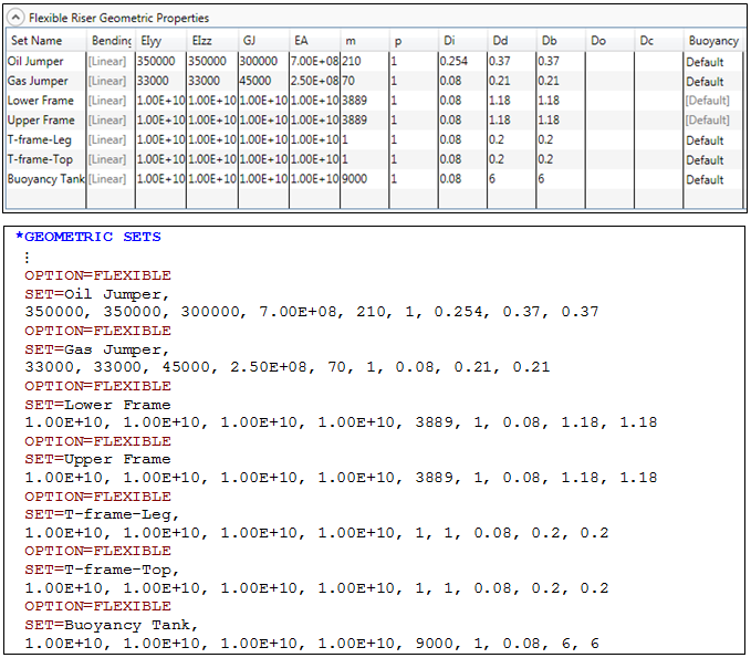
Structural Properties – Flexible Riser Format
Refer to the *GEOMETRIC SETS keyword for further information on these data inputs.
The structural properties of a flex joint are characterised in terms of a rotational stiffness, and it may optionally have associated weights in air and in water. The upper and lower flex joints for this example are assigned properties as shown in the figure below. Refer to Hinges and Flex Joints for further information on this feature.
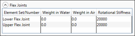
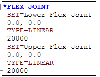
Flex Joint Properties
Refer to the *FLEX JOINT keyword for further information on these data inputs.
The simplest hydrodynamic property specification in Flexcom is that of constant coefficients, which remain the same throughout an analysis. Five hydrodynamic coefficients are specified on an element set by set basis. For simplicity, all elements in this example are assigned the same hydrodynamic coefficients as shown in the figure below. Refer to Constant Hydrodynamic Properties for further information on this feature.
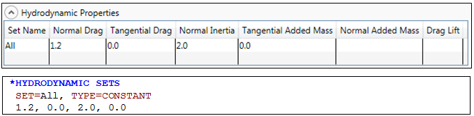
Hydrodynamic Properties
Refer to the *HYDRODYNAMIC SETS keyword for further information on these data inputs.