Boundary Conditions |
 
|
Boundary Conditions |
|
Flexcom presents a comprehensive range of options to fully describe the constraints which are applied to the finite element model. The various options include constant (time invariant constraints), vessel (to apply vessel motions), and several others including an arbitrary user-subroutine facility which provides for complete generality in terms of constraint application. The first two options are invoked in this example, with the base of the central structure fixed in all degrees of freedom, and the upper ends of the jumper hoses attached to the FPSO, as shown in the first and second figures below, respectively. Note that the relevant node labels (i.e. Seabed End, Oil Jumper FPSO and Gas Jumper FPSO), created automatically by the lines facility during model building, are referenced when defining boundary conditions. The specification of boundary condition data goes into the $LOAD CASE section of the file. Refer to Boundary Conditions for further information on this feature.
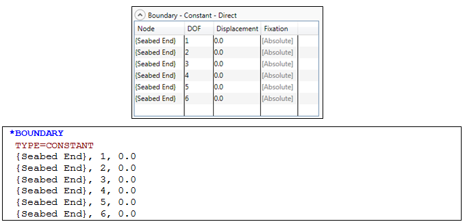
Constant Boundary Conditions
Note that that symbol ![]() indicates that the following keyword data is supplementary to the existing data under the same keyword as shown previously.
indicates that the following keyword data is supplementary to the existing data under the same keyword as shown previously.
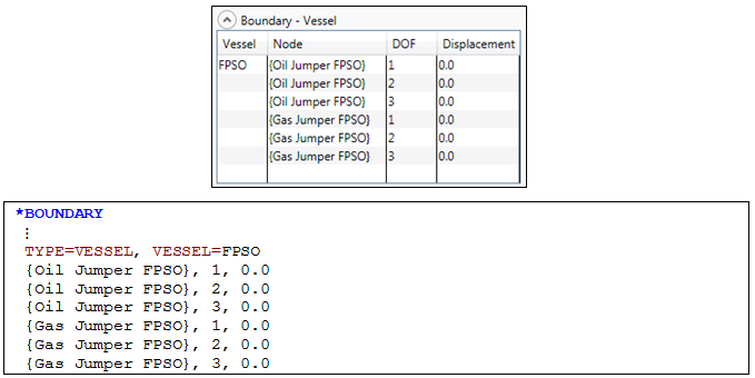
Vessel Boundary Conditions
Refer to the *BOUNDARY keyword for further information on these data inputs.