Model Summary |
 
|
Model Summary |
|
This example considers an internal turret moored FPSO in 150m of water. The internal turret is modelled as a large cylindrical structure, fixed to the vessel and positioned within the cylindrical moonpool. The turret connects 5 risers and 1 umbilical, in a lazy wave configuration, to the FPSO. Contact with the moonpool frame is also modelled via eight perpendicular, cylindrical guide surfaces positioned around the turret.
The turret is moored with a 6 leg chain mooring configuration arranged in 3 bundles of 2 legs each. The two adjacent legs in each bundle are separated by 10°, with 120° between each bundle axis. The mooring spread is 300m and each leg has a length of 370m. This is done easily in Flexcom by defining angles in the *PARAMETERS command in terms of the mooring spread radius and angles. The connection at the buoy is modelled with a hinge element in order to avoid the transfer of any moment or torsion into the buoy.
The turret frame is modelled with eight cylindrical guide surfaces arranged symmetrically. The guide surfaces are defined in a similar fashion as the mooring lines in terms of a radius and radial coordinates. From here, the guide surfaces are defined using the *GUIDE keyword using an origin, and two perpendicular axial and radial vectors. This is shown in the figure below. For the ease of defining the radial vector, a subtended angle of 360 has been used.
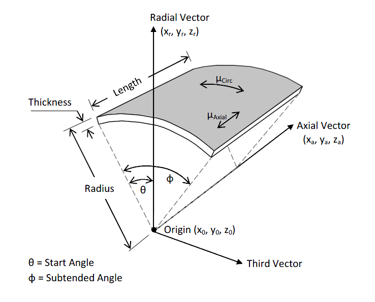
Cylindrical Guide Surface Definitions
The turret body is modelled as large diameter, stiff beam elements, with stiff connection elements connecting the risers and moorings to the buoy. Mass and inertia properties are defined using the *FLOATING BODY keyword. Additionally, in order to appropriately model the tangential hydrodynamics and mass distribution, the buoy has been divided into an upper, middle and lower section element sets.