Model Summary |
 
|
Model Summary |
|
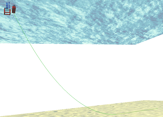
The first figure below shows the system that is being modelled here. The seabed has a slope of 2o. The transfer analysis starts from the point where the end of the SCR has been lowered by the installation vessel winch below the wave zone, and the vessel has been rotated beam-on to the host platform. Both the payout winch (on the installation vessel) and the pull-in winch (on the host platform) are modelled using winch elements. The second figure below shows a close-up of the installation vessel and the host platform.
SCR Transfer Model
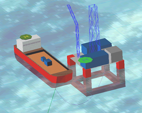
Installation Vessel and FPU
The three figures below illustrate the transfer procedure. The first figure below shows the system at the start of the analysis. The installation vessel has transferred some of the load to the host platform in the second figure. Finally in the third figure the host platform has assumed the full load of the SCR and the installation winch slackens and is eventually disconnected.
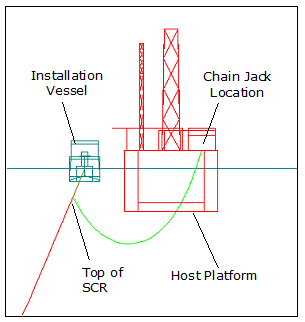
Vessel Supports SCR Load
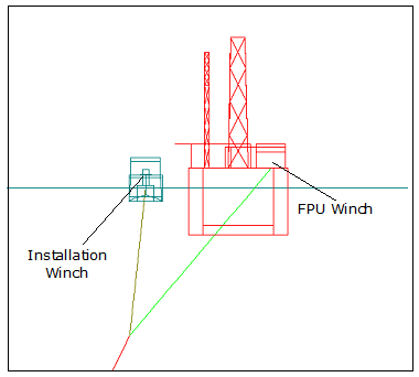
Transferring SCR Load
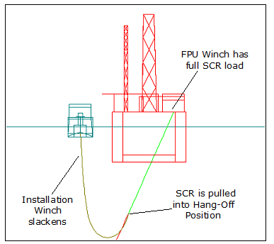
FPU Supports SCR Load
Bending stresses, von Mises stresses and bending strains along the SCR, particularly in the sagbend region, cannot exceed allowable values.
Winch elements are normal beam-column elements which have the unique property that their lengths can vary during an analysis. In a dynamic analysis, the variation in length is defined in terms of a maximum winch velocity and a winching time sequence. The time sequence consists of (i) a ramp-up time when winch velocity is increased from zero to the maximum value; (ii) a time during which the velocity remains at this maximum, and (iii) a ramp-down time when the velocity returns to zero. The operation in a static analysis is less complex, with an overall change in length being applied linearly from the analysis start time to the end time. Winch elements can be used, for example, in pipelaying applications, for example in simulating the transfer of an SCR from a lay vessel to a TLP or semi-sub.