Model Summary |
 
|
Model Summary |
|
This section contains information on:
This example demonstrates the analysis of a multiple riser system in shallow water. The riser system consists of three production risers and two water injection risers, all of which are connected to the FPSO which is aligned with the risers. The system is sited in 85m of water and each riser passes over the subsea mid-water arch. The production risers are 260m long and are filled with oil. The water injection risers are 1m longer in the upper catenary section and are filled with seawater.
The analysis is performed in three stages. The static configuration of the system, subjected to gravity and buoyancy loading, is established in the initial static analysis where the mid-water arch is held in position using boundary conditions. A subsequent static restart analysis is performed to release the arch by removing these boundary conditions. Finally, the dynamic analysis finds the response of the system to regular wave loading.
The mid-water arch model is composed of a framework of beam elements connected to a series of curved guide surfaces and two buoyancy tanks, all of which are tethered to the seabed. The model is highly parameterised using the *PARAMETERS keyword. The arch is modelled as a function of several parameters, the riser diameters, the midwater arch frame width, curved guide radius and subtended angle.
The riser diameters are stored in the parameters L1_Do to L5_Do. Changing the value of the outer diameter will change dependant parameters such as the length of the curved guide surface under that riser as well as the gutter gap and its curvature.
The frame width is defined as the distance between the two buoyancy tanks (centre-to-centre) and is stored in the parameter FrameWidth. Changing the value of this parameter will change the overall shape of the arch and the associated top guide surfaces as well as the gutter wall heights and lengths.
The side guide surfaces are defined by two parameters, the radius and subtended angle, stored in the parameters SideGuideRadius and SideGuideSubtAng respectively. Again, the shape of the arch can be affected by changing these parameters.
Also parameterised is the tether height and bridle length to facilitate easy adjustment of the arch in the vertical direction.
The mid-water arch is built around the origin of the global axis system, such that the axes are located as shown in the figure below. There are three curved guide surfaces supporting each riser, one top and two side curved guide surfaces, one vessel side and one well side. The curved guide surfaces, defined using the *GUIDE keyword and TYPE=CYLINDRICAL option, are connected to the frame by beam elements and driver nodes. The risers are defined in three sections, the lower and upper catenary sections (defined using the *LINES keyword) and the central section of riser which passes over the arch (defined using individual nodes and elements). The arch section nodes are parameterised so as to follow the curved arch, a distance of the riser radius above the arch, so as to facilitate ease of initial static solution. The riser is connected to the mid-water arch with a hinge element representing the friction clamp which is used to keep risers in place. It is also possible to remove this hinge element to allow the riser to move freely over the arch to model a situation where the friction clamp may have failed. The sections of the catenary lines which can potentially come into contact with the arch are prescribed a finer mesh to accurately capture contact on the arch region. The lower catenary risers are supported on an elastic seabed while the upper portions of the risers are connected to the FPSO.
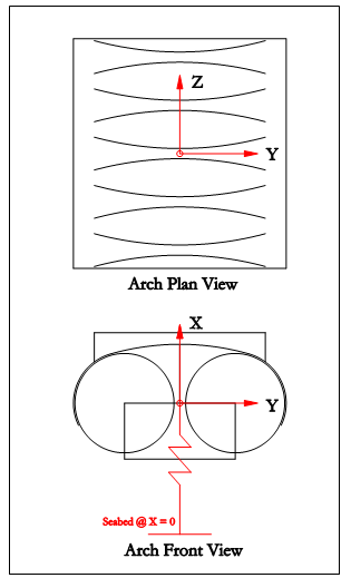
Global Axis System in relation to Midwater Arch
The hydrodynamic properties of the mid-water arch are very different in the vertical and horizontal directions, therefore the arch hydrodynamic coefficients are normally specified separately for each of three directions (one vertical, two horizontal). Furthermore, for each direction the data is often specified as three products, namely:
i.CdAd (drag coefficient by frontal area) for the hydrodynamic loading due to relative fluid/arch velocity.
ii.CmVin (inertia coefficient by reference volume) for the hydrodynamic loading due to arch acceleration.
iii.CaVin (added mass coefficient by reference volume) for the hydrodynamic loading due to water particle acceleration.
This means a mid-water arch may be characterised by nine hydrodynamic coefficients or products. Flexcom transforms the arch data specified in terms of these nine coefficients into equivalent hydrodynamic properties for each element of the arch structure set, and the analysis then proceeds in the usual way. In this way phase differences between wave forces on different parts of the arch, and also the changes in the arch hydrodynamic properties as the arch displaces and rotates, are very accurately modelled.