Video Library |
 
|
Video Library |
|
These videos provide sample illustrations of Flexcom's modelling capabilities and broad range of applications.
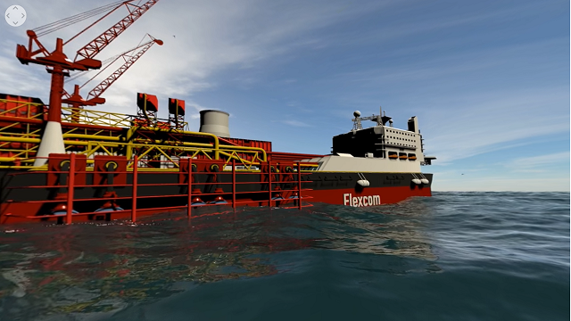
Offshore production system. This system is based on a free standing bundled hybrid tower concept, which is typical of deep water production systems deployed in West of Africa field developments. Oil is transferred to the FPSO using a set of flexible jumpers, and from there to the CALM buoy via two offloading lines which hang in a wave type configuration. Both the FPSO and the CALM buoy are held on station using chain and steel wire mooring lines. Several flowlines are located on the seafloor and connected to the vertical tower using an arrangement of rigid spools. Although this model is very complex and contains over 3000 elements, it is very easy to assemble in Flexcom using the line modelling feature. Flexcom also provides a high accurate pipe-in-pipe modelling feature which has underpinned the engineering design of some of the world's most complex riser bundle configurations. Flexcom has a detailed internal flow model, catering for centrifugal, coriolis and dynamic pressure effects. The internal fluid contents may also vary over time, in order to accurately simulate intermittent slug flow. |
|
Flexible riser system. The model contains 5 flexible risers, which pass over a tethered mid-water arch in a lazy-S configuration, and is typical of the shallow water production systems deployed in North Sea field developments. The mid-water arch itself is modelled as a rigid frame structure, which supports an arrangement of contact surfaces. Uplift is provided by two large buoyancy tanks which keep the tethers in tension, and help to stabilise the entire system. Flexcom’s renowned computational technique provides high levels of confidence in the engineering design. Although the time domain simulation is relatively detailed, including intermittent contact with curved surfaces, the entire simulation may be completed in just a few minutes. See Example C02 - Multi-Line Flexible System for further information. |
|
Floating Offshore Wind. This is one of the reference models used in the international research project OC4. OC4 is sponsored by the International Energy Agency and coordinated by NREL. It benchmarks a variety of simulation software for modelling of offshore wind turbines, both fixed and floating. Results from the Flexcom model show very good agreement with published data, in terms of platform motions, mooring line tensions, tower base moments, nacelle accelerations etc. Aerodynamic outputs such as generator power and rotor speed also show close agreement with other modelling tools. See Example L01 - OC4 Semi-Submersible for further information. |
|
Turret disconnect. This is an operation which is performed in harsh environments caused by inclement weather conditions. The model includes a turret moored FPSO, 6 mooring lines, 2 production risers, 2 water injection risers, a gas lift line and an umbilical. The turret itself is modelled as a frame type structure, with rigid connections linking it to each of the attached lines. The turret is disconnected from the FPSO and allowed to sink into the ocean. Contact with the circular vessel moonpool is also monitored using an arrangement of contact surfaces positioned around the turret. See Example C03 - Turret Disconnect for further information. |
|
J-Tube pull-in. The J-Tube is a curved conductor which is rigidly attached to a fixed platform, and through which a flexible riser is installed. One end of the flexible is attached to a winching cable which is inside the J-tube. The winching process is modelled using Flexcom’s winch element feature, which allows paying-out or reeling-in operations to be simulated. The interaction between the flexible and J-tube is modelled using Flexcom’s pipe-in-pipe modelling facility. Sliding connections are used in this model, with the software continually monitoring and updating the connected nodes as the analysis progresses. See Example H02 - J-Tube Pull-In for further information. Independent studies have shown a strong correlation between Flexcom and general purpose finite element software for this type of analysis. Furthermore, the authors conclude that the solution provided by Flexcom offers greater efficiency, both in terms of ease of model set-up, and significantly reduced computational times. |
|
Dropped object. This model contains a flexible riser arranged in a steep wave configuration, which is connected to an FPSO. A support vessel is docked alongside the FPSO, and a freight container accidentally drops from the crane and sinks down into the ocean. Contact between the falling container and the flexible riser is modelled using Flexcom’s line clashing feature. Clashing is a complex and highly non-linear phenomenon, so the use of relatively small time steps is essential, in order to accurately capture the moment of impact, and the subsequent structural response. Flexcom automatically reduces the solution time step in anticipation of contact, and once the components have separated after impact, the time step begins to increase again. This approach facilitates a robust and accurate contact model, while also ensuring an efficient simulation. In order to accurately capture the deformation of the flexible riser, relatively short elements are used in the contact region. Numerical damping is typically used to simulate energy dissipation during the collision. See Example J01 - Dropped Object and Recovery for further information. |
|
Dropped riser. This video illustrates a dropped riser assessment performed using Flexcom. A drilling riser is accidentally released from a drillship and collapses onto the seabed below. The objective of the study is to assess potential lateral excursions of the riser and to estimate a likely envelope of final horizontal spread. There is significant compression in the riser upon impact and Flexcom is capable of modelling the onset of buckling and the post-buckling response. Self-contact between different portions of the riser is not modelled for computational efficiency, but this could be captured using the line clashing modelling feature if required.
|
|
Fixed Offshore Wind. This is one of the reference models used in the international research project OC4. OC4 is sponsored by the International Energy Agency and coordinated by NREL. It benchmarks a variety of simulation software for modelling of offshore wind turbines, both fixed and floating. Results from the Flexcom model show very good agreement with published data, in terms of shear forces and bending moments, and structural deflections in the jacket structure. See Example L03 - OC4 Jacket for further information. |
|
Drilling Riser. This is a deep-water riser, typical of deepwater exploration systems deployed in regions such as the Gulf of Mexico. The model simulates an emergency disconnect scenario, following failure of the dynamic positioning system on the drillship. In such situations, the riser is quickly disconnected from the wellhead to prevent any potential damage. See Example A01 - Deepwater Drilling Riser for further information. Although Flexcom can provide an approximate simulation of the disconnect event, a more comprehensive simulation may be performed using DeepRiser DeepRiser, which specialises in the analysis of top-tensioned risers. DeepRiser provides a detailed hydro-pneumatic tensioner, which models all the major hydraulic and pneumatic components. It can model each tensioning cylinder independently, and can simulate the behaviour of the anti-recoil control system. It also incorporates an advanced fluid flow model, based on a finite volume numerical technique, to model the drilling mud exiting from the base of the riser. |
|
Pipe Laying. This is a complex installation procedure, as the pipeline is laid down over a steep subsea precipice. The winching process is modelled using Flexcom’s winch element feature, which allows paying-out or reeling-in operations to be simulated. Flexcom possesses a powerful seabed modelling facility which can handle complex topographies with ease. The user simply specifies an arbitrary cloud of data points, and Flexcom’s triangulation algorithm automatically generates a continuous seabed profile. Although this simulation was performed using Flexcom, Wood Group also offer a dedicated installation software package called PipeLay. PipeLay provides a comprehensive set of technical features which are specifically designed for installation analysis, including rapid generation of fixed and floating stinger profiles, and a range of options for modelling rollerbox support contact. PipeLay also facilitates automatic adjustment of support elevations to achieve specified curvature limits, saving time for installation engineers. |
|
Steel pipe installation with plastic deformation. This model considers the installation of a steel pipe which experiences plastic deformation as it passes over the vessel stinger and is landed onto the seabed. J-Lay installation is typically used in deep water but this model uses an S-Lay configuration as it leads to high levels of bending strain as the pipe passes over the stinger. So the example is somewhat artificial as it is specifically crafted in order to illustrate Flexcom’s ability to model plastic deformation. Significant bending strain is experienced as the pipe deforms over the stinger under its own self weight during the payout. The residual strain is evident as the vertical section of pipe which hangs off the stringer, is clearly not straight as it is lowered down through the water column. Localised concentrations in bending strain are highlighted on screen by colour contouring. Once the pipe reaches the seabed, the lower end is fixed using a pinned boundary condition and the vessel begins to move forward while payout continues. As the laydown progresses, the pipe starts to straighten out and eventually the direction of curvature fully reverses from hogging to sagging as the pipe profile adopts an S-lay shape. A lot of residual strain remains post-installation. See Example H05 - Steel Pipe Installation with Plastic Deformation for further information. |
|
Floating hose. This hose is used to offload oil from a semi-submersible platform to an FPSO. Floating hose models are extremely sensitive to wave loading, as the entire model is located in the water surface region. Flexcom provides a detailed buoyancy formulation, which accounts for the partial submergence of the hose. The submerged volume of each element is computed based on the instantaneous water surface elevation and the local penetration angle. Flexcom also automatically increases the number of integration points within every surface piercing element. This ensures a precise distribution of the applied hydrodynamic forces. See Example E03 - Floating Hose for further information. |
|
Tower Crane & Pulley System. The crane lifts a 10ton block from the ground up to an elevation of 14m. A 32mm wire rope is used, designed to support a safe working load of almost 12tons. The pulley diameters are set equal to 40 times the cable diameter. The tower is equipped with 3 pulleys on the hoist, two at the end of the jib, and one at the lower end of the hoist close to the hook/weight. Another pulley close to the tower facilitates the lifting process. The cable is reeled onto the tower pulley at a constant rate of 0.1m/s. The pulleys are modelled using cylindrical guide surfaces with relatively high contact stiffness to prevent any significant penetration of the pulley surfaces by the cable. The tower pulley in particular, has a very high contact stiffness which is capable of withstanding the compressive radial loads exerted by multiple wraps of cable as the block is lifted upwards. The upper end of the cable is attached to a rigid frame within the tower pulley. The frame and pulley are rotated at a constant speed using a time history file, causing the cable to wrap itself around the contact surface. The mesh density is relatively fine in order to model the cable-pulley interaction in sufficient detail. See Example J05 - Tower Crane & Pulleys for further information. |
|
Wave Energy Converter. This device is known as 'DUO', developed by Pure Marine Gen. Its innovative nature has led to it being shortlisted as a finalist in the U.S. Department of Energy’s Wave Energy Prize. Empirical results from model-scale tank tests have shown a strong correlation with numerical simulations performed using Flexcom. The software uses coupled analysis to model WECs, including high and low frequency wave forces, added mass, radiation damping, and viscous drag. Flexcom can also simulate the power take-off using a combination of non-linear spring and damper elements, presenting the designer with key information regarding power output and energy generation. According to Dr Paul Brewster, C.T.O. at Pure Marine Gen, “the advances in simulation capabilities that Flexcom provides have enabled the development and validation of DUO, and the step-change improvements in performance make wave energy a commercial reality”. |
|
Mid-Water Arch Tether Failure. This video shows a mid-water arch tether failure being simulated by Flexcom. The arch is initially horizontal but gradually rotates into a vertical orientation following the failure of one of the tethers. The model was created by Wood’s subsea engineering team for a third-party client as part of an engineering task force response to a real-world incident. The second half of the video shows the system response to wave loading with the arch in its damaged configuration. The risers remain connected to the arch in their original slots despite the 90degree rotation of the arch. Unfortunately this video has no sound but the visuals are very interesting nonetheless!
|
|
Torsion-induced riser pigtailing. Wood Group undertook an investigation into some unusual freespans which had developed in risers and jumpers following the completion of subsea tie-in operations. Based on freespan analysis performed using Flexcom, the team were able to numerically reproduce the deformed geometry which had been observed in reality. The characteristic “pigtail” response, which you can see in the video, is caused by torsional loading in the riser. In this particular model, the torsional load was induced by applying a forced rotation at the flange connection. Flexcom is capable of accurately simulating the structural deformation due to its specialised finite element formulation, which fully accounts for coupling between the bending, torsional and axial degrees of freedom. Based on the Flexcom results, both the minimum bend radius and the maximum torque, were found to be within allowable limits. A subsequent slug load fatigue assessment also demonstrated that the predicted fatigue life is also acceptable.
|
|
Flexible risers crossing and hooking together. This model examines how flexible risers can cross over each other and become hooked together when a mid-water arch system is subjected to cross (90 degree) current and wave loading. For ease of viewing, some risers are hidden, so you can more clearly see the water injection riser (blue and purple) crossing over the production riser (white/grey) and becoming hooked around it. Stress contouring shows the elevated bending moments experienced by the water injection riser during and following the interaction.
|
|
|
Experience a Flexcom model in 3D Virtual Reality Environment. The Unity Plug-In allows users to create more advanced visualisations than is possible within Flexcom itself. It allows you to transfer results from a Flexcom database into the Unity environment, which means that the enhanced display is based on the motions derived from the finite element simulation. This feature may be used to create promotional videos which highlight innovative device concepts or service offerings. Such videos are also VR-ready, so computational models can be experienced a fully-immersive virtual reality environment. Virtual reality environments are normally provided by means of a specialised headset, which is supported by a high performance computer. However you can also experience a similar, albeit slightly lower spec version, using a standard smartphone and a cardboard headset. Open one of the links below on your smartphone using YouTube, set the view mode to ‘Cardboard’, set the quality to ‘High Definition’, and then pop on the cardboard headset. Once you’re in the VR environment, you can adjust your viewing direction by physically turning around or looking up or down. The main limitation is that you cannot fly to different locations within the 3D space – your position in space is effectively static – which is why we have created two separate locations for you to explore, one above the water surface and one subsea. |
More interesting videos are also available on the Flexcom channel on YouTube.