Bending Stress |
 
|
Bending Stress |
|
Bending stress in an element cross section is defined by the equation below, with reference to the Bending Stress Calculation figure below. Note that the maximum bending stress occurs at the outer surface of the cross section.
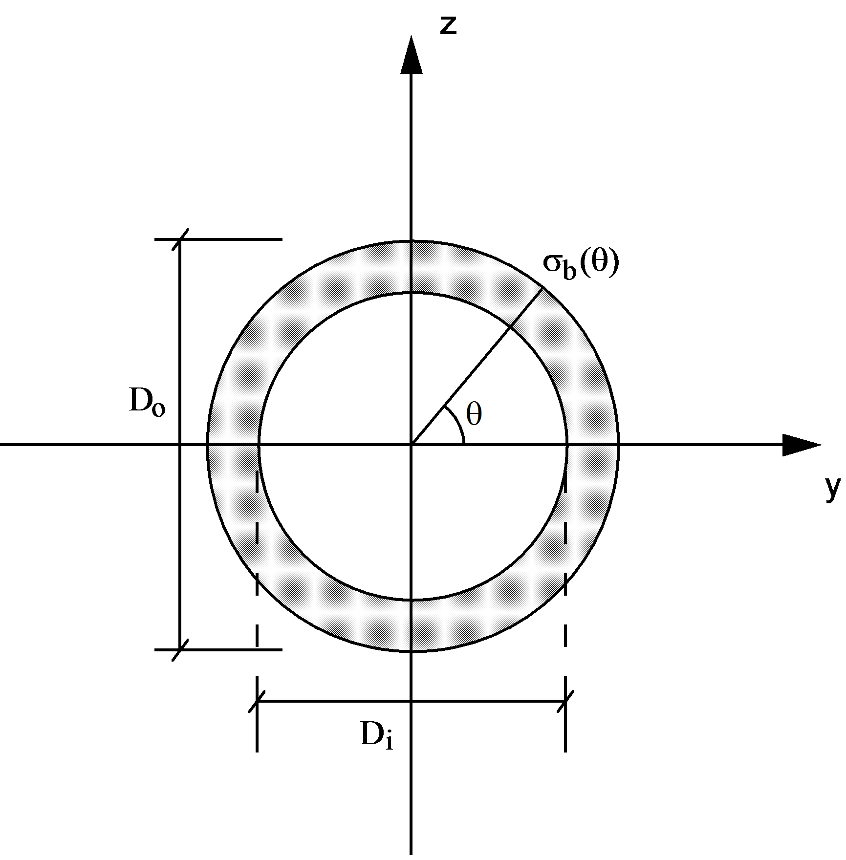
Bending Stress Calculation
where:
•![]() is the bending stress for an angle θ as defined in the figure above
is the bending stress for an angle θ as defined in the figure above
•My and Mz are the bending moments about the local y- and z-axes, respectively
•Iyy and Izz are the second moments of area about the local y- and z-axes, respectively
• Do is the effective outer diameter
By default, Flexcom outputs the maximum bending stress occurring on the cross section. However, when you request a plot of bending stress, you can optionally specify a location around the element circumference where bending stress is to be computed. The location is specified in terms of an integer value (N) which corresponds to an angle θ, measured in degrees anti-clockwise from the local element cross-section y-axis. The table below indicates the variation of parameter N with θ for bending stress calculations. In this table, σB represents bending stress.
Location Parameter for Bending Stress Calculations
θ° |
N |
0 |
1 |
45 |
2 |
90 |
3 |
135 |
4 |
180 |
5 |
225 |
6 |
270 |
7 |
315 |
8 |
Since maximum bending stress must occur on the riser outer surface, only values for n between 1 and 8 are required (or valid).
If you do not explicitly specify a location N, Flexcom outputs the maximum bending stress occurring on the cross section. The maximum value of σb can be found from the Equation above by setting ![]() . The value of θ corresponding to the maximum bending stress is given by:
. The value of θ corresponding to the maximum bending stress is given by:
 (2)
(2)
When Iyy = Izz, as is normally the case, the Equation directly above reduces to:
 (3)
(3)
Flexcom calculates maximum bending stress using the Equations above.