Reference Point Boundary Conditions |
 
|
Reference Point Boundary Conditions |
|
Reference point boundary conditions are used where the motion of a point or points on the structure is defined by the motions of a point not on the structure known as a reference point. These boundary conditions are analogous to vessel boundary conditions, with the exception that the motion of the reference point is read in this case from an ASCII data file, rather than being determined from RAOs and ambient wave elevation. Effectively what happens during an analysis is as follows. The location and orientation of the reference point is read from the ASCII data file at the start of the analysis. The static displacement (this is an optional entry associated with reference point boundary conditions), if present, is applied at the boundary node(s). Any subsequent change in the location and orientation of the reference point from the position at the start of the analysis is applied to the relevant node and DOF as if a rigid link existed between the reference point and the location of the node after static displacement. Flexcom uses cubic spline interpolation to find the location and orientation of the reference point at time points between those specified in the data file (for this reason the analysis solution times do not need to match those in the data file). Note that the reference point need not be a point on the structure – in general it is more likely to be, say, the centre of gravity of an attached floating structure. For analysis times before the earliest time in the data file, Flexcom uses the location and orientation of the reference point at that earliest time. Similarly, for analysis times after the latest time in the data file, Flexcom uses the location and orientation of the reference point at that latest time.
The ASCII data file contains seven columns of data. The first column contains time data, and the remaining six correspond to the six degrees of freedom defining the position and orientation of the reference point. Comment lines, denoted by a capital ’C’ in the first column, are permitted, while lines that are completely blank are ignored. An example data file is shown below.
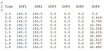
The first column of data contains time values. Columns 2 – 4 contain the global X, Y and Z coordinates of the reference point, while Columns 5 – 7 contain the components of the rotation vector (in degrees) describing the orientation of the reference point. These columns correspond to degrees of freedom 4 – 6 of the Flexcom coordinate system.
Flexcom provides a number of options for specifying vessel motions to be read from timetrace files, which mostly operate in similar fashion to this facility. Indeed the enhanced vessel motion options could be considered to supersede this earlier feature, which is retained though for compatibility with previous program versions. You are of course perfectly entitled to continue using the reference point boundary capability as required.
Relevant Keywords
•*BOUNDARY is used to define boundary conditions. Specifically, the TYPE=REFERENCE input is used to identify the nodes on the structure whose time-varying motions are to be calculated from the motion of a so-called reference point.