|
*Drift |
 
|
*Drift
|
*Drift |
|
To define vessel drift motions.
Refer to Low Frequency Drift Motions for further information on this feature.
A block of two lines repeated as many times as necessary to define all the vessel drifts. The first line specifies the vessel name and drift type.
VESSEL=Vessel Name, TYPE=Drift Type [, OPTION=Axis System]
The format of the second line depends on the drift type.
For drift motions read from a timetrace file:
FILE=File Name
For sinusoidal drift:
Drift DOF, Amplitude, Phase, Period
A vessel may not be assigned both timetrace drift and sinusoidal drift. Timetrace drift is not relevant for frequency domain dynamic analysis. Drift Type can be SINUSOIDAL or FILE. Axis System can be GLOBAL (the default) or LOCAL. File Name should include the entire path of the vessel drift motion file including its extension. If the file name or any part of its path contains spaces then it should be enclosed in double quotation marks.
To specify that vessel drift or low frequency motions are to be read from an ASCII timetrace file, and to specify the file name.
Input: |
Description |
Vessel: |
The name of the vessel for which drift data is being input. |
Timetrace File Name: |
The name of the ASCII data file containing the timetrace of low frequency motion of the vessel reference point. Timetrace File Name should ideally include the entire path of the vessel drift motion file, including extension. If the name or any part of its path contains spaces, the full File Name should be enclosed in double quotation marks (" "). |
Axis Type: |
The options are Global (the default) and Local. |
(a)The format of the drift timetrace file is as follows. The file contains seven columns of data. The first column contains time data, and the remaining six correspond to displacements of the reference point in six degrees of freedom. Comment lines, denoted by a capital ‘C’ in the first column, are permitted, while lines that are completely blank are ignored. An example data file extract is shown below.
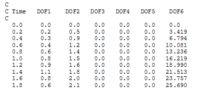
The first column of data contains time values. Columns 2 – 4 contain the displacements (not coordinates) of the reference point from its initial position at the start of the dynamic analysis. This means that the data in the timetrace file should not include the value of any static offset you apply to the vessel. If it does, what will happen is that the offset will be applied twice. These displacements are in either the global XYZ axes or else in a local axis system defined by the initial orientation of the vessel – you specify which using the Vessel Motions – Axis Type option. Columns 5 – 7 contain rotations in degrees. Column 5 contains the yaw rotation of the vessel about the vertical or global X axis. Columns 6 and 7 are roll and pitch respectively, relative to either the yawed or initial vessel axes, depending on whether large or small angle theory is specified. Note that each line of the file (other than comment lines or blank lines) must contain 7 numerical values.
Flexcom uses cubic spline interpolation to find the displacements and rotations of the reference point at times intermediate to those specified in the data file (for this reason the analysis solution times do not need to match those in the data file).
(b)The choice of axis system refers to data you specify for vessel drift motions. Motions in this context means translations only – rotations always refer to vessel axes. Naturally Global stipulates that translations represent drift or combined motions in any or all of the global X, Y or Z axes, and/or that the angle you specify in defining a constant velocity is relative to global Y. Conversely Local indicates that translations represent any or all of heave, surge or sway, defined with reference to the initial orientation of the vessel axes, or that the angle you specify in defining a constant vessel velocity is relative to the vessel surge axis.
To specify sinusoidal vessel drift or low frequency motions.
Input: |
Description |
Vessel: |
The name of the vessel for which drift data is being input. |
DOF: |
The degree of freedom (DOF) of the vessel drift motion. Specify a value of 1, 2 or 3 for a translation in the global or local axes, depending on the Axis System you nominate. A value of 4 represents a rotation about the global X axis, while 5 and 6 are low frequency roll and pitch respectively relative to either the yawed or initial vessel axes, depending on whether large or small angle theory is specified. |
Amplitude: |
The amplitude of the sinusoidal drift. A non-zero positive value is required. |
Phase: |
The phase in degrees of the sinusoidal drift, which defaults to 0. See Note (b). |
Period: |
The period in seconds of the sinusoidal drift. A non-zero positive value is required. See Note (c). |
Axis Type: |
The options are Global (the default) and Local. |
(a)This sinusoidal drift facility is similar to the boundary conditions option offered via the Boundary – Sinusoidal (time domain) and Boundary – Harmonic (frequency domain) options. However, the data specified here defines the drift motion of a vessel reference point whereas the boundary condition options directly apply a sinusoidal motion to a node of the finite element discretisation.
(b)In the time domain, this input simply relates or ties the drift time variation to the time datum. A sinusoidal drift is actually applied as a cosine wave, so if the default phase value of 0o is specified, the first maximum value of drift response occurs at time t=0s.
(c)In the frequency domain, the period of drift motions is very often outside of the range of harmonics in a wave spectrum. However there is no requirement on you to invoke the Wave – Frequencies option to force Flexcom to include a harmonic in a random sea discretisation at the drift frequency (or frequencies) you input here. The program does this automatically, without user intervention.
(d)The choice of axis system refers to data you specify for vessel drift motions. Motions in this context means translations only – rotations always refer to vessel axes. Naturally Global stipulates that translations represent drift or combined motions in any or all of the global X, Y or Z axes, and/or that the angle you specify in defining a constant velocity is relative to global Y. Conversely Local indicates that translations represent any or all of heave, surge or sway, defined with reference to the initial orientation of the vessel axes, or that the angle you specify in defining a constant vessel velocity is relative to the vessel surge axis.