Model Summary |
 
|
Model Summary |
|
The drilling riser is fixed at the base of a tapered stress joint to a subsea wellhead via a subsea connector. Above the stress joint, the stack-up comprises 23 standard riser joints, the lower fifteen of which are fitted with buoyancy foam. Between the top of the standard riser joints and the tensioner spool joint are a pup joint, a lower centraliser joint and the inner riser housing and adapters. The riser tensioning ring and a centraliser are located on the tensioner spool joint at mid-height and at the top of the joint respectively. A BOP and slip joint are fitted above the tensioner spool joint. The Drilling Riser Stack-Up Schematic figure below shows a schematic of the drilling riser stack-up.
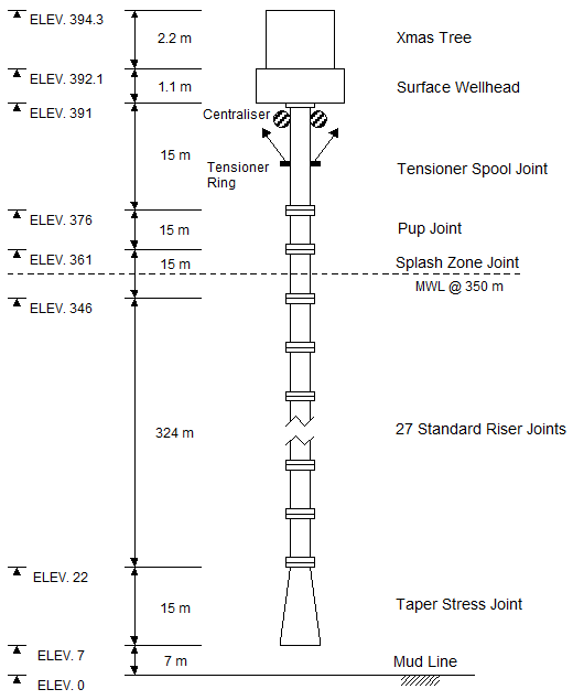
The production riser under consideration is of the dual casing type with the outer annulus containing brine and the inner annulus containing gas. A tapered stress joint is located at the riser base, above which are 27 standard riser joints. Above the standard riser joints, at the MWL, is a splash zone joint and above this are located a pup joint, the tensioner spool joint, surface wellhead and Xmas tree respectively. The riser tensioning ring is located midway along the tensioner spool joint and a centraliser is located at the top of this joint also. The Production Riser Stack-Up Schematic figure below shows a schematic of the production riser stack-up.
The TLP vessel is approximately 75 m long by 75 m wide with a draft of 30m, and is connected to the seabed with tethers of length 300 m.

Drilling Riser Stack-Up Schematic