Results |
 
|
Results |
|
The first figure below shows the distribution of effective tension in the riser after the current analysis. The tensioning effect of each of the three air cans is evident, as is the transfer of load from the keel sleeve to the riser at the top of the keel joint.
The second figure below shows the distribution of static resultant bending moment in the riser. Note the peak in bending moment around the location of the keel joint. This indicates that, as the vessel has been offset horizontally, the contact between the keel sleeve and its lateral guide has resulted in a horizontal contact reaction that gives rise to the peak in bending moment.
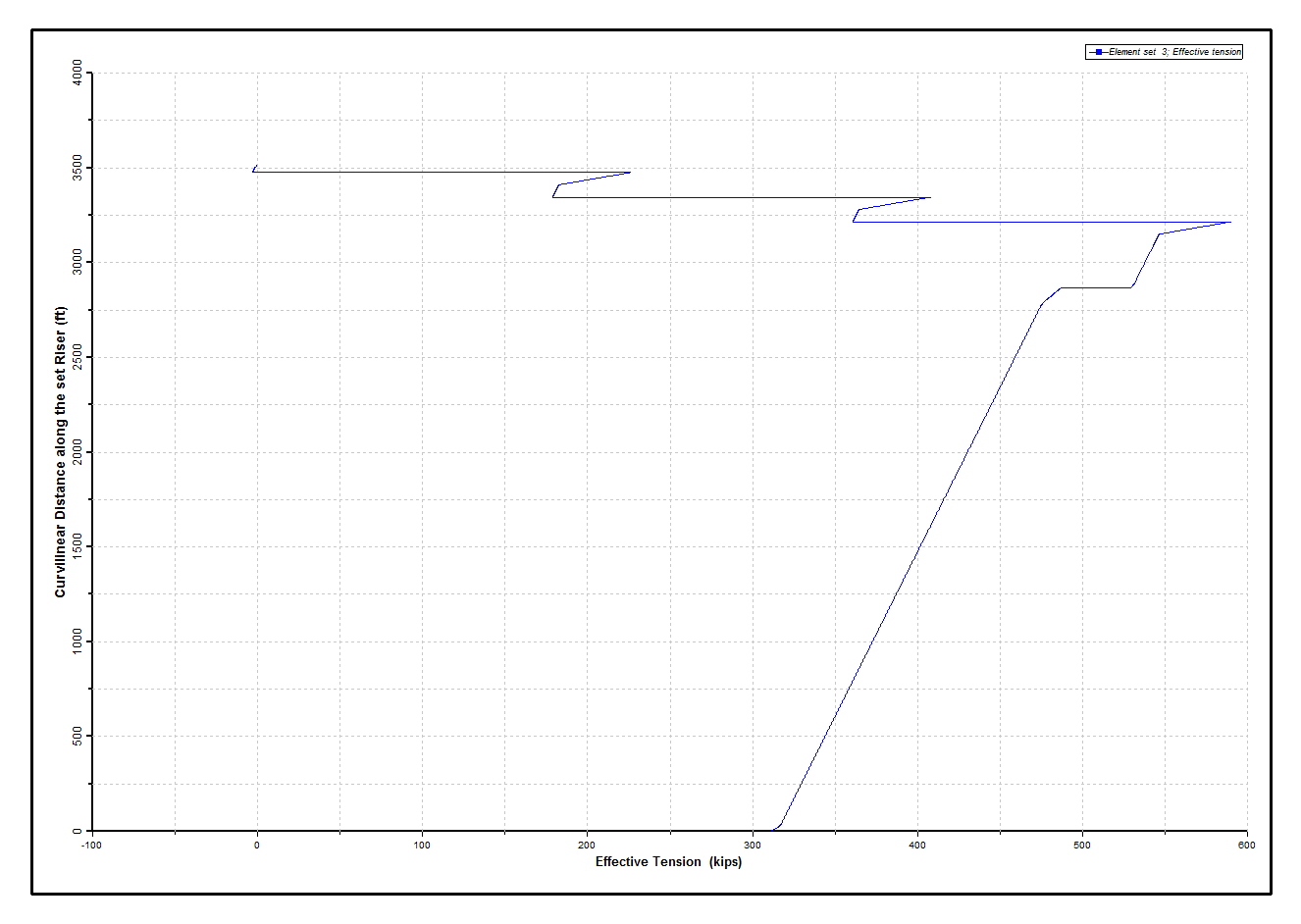
Static Effective Tension
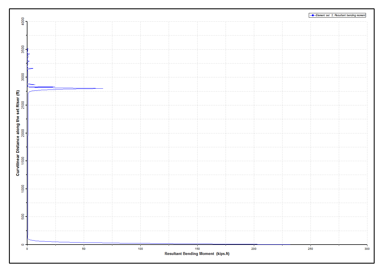
Static Resultant Bending Moment
The envelopes of dynamic effective tension in the riser are plotted in the figure below, which shows a relatively small variation in effective tension over much of the riser for the dynamic analysis.
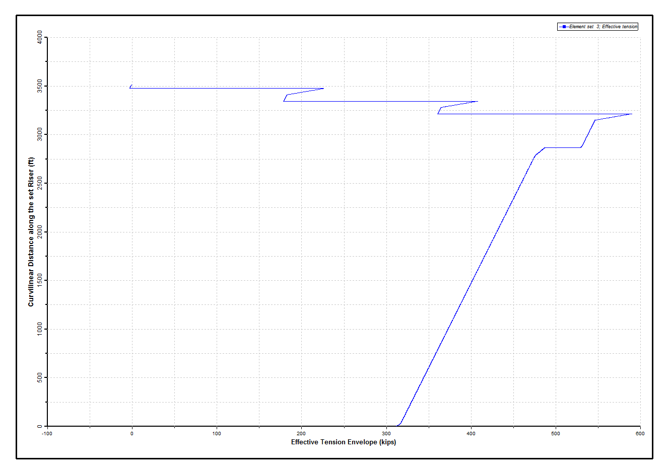
Effective Tension Envelope
The first figure below plots envelopes of von Mises stress. Note the peaks in stress in the region of the air cans, which can be largely attributed to areas of locally high bending moment resulting from contact between the air cans and lateral guides. Finally, the second figure below shows the dynamic bending moment envelopes. Comparison with the Static Resultant Bending Moment figure above shows that contact is now occurring at the air cans in addition to the keel joint.
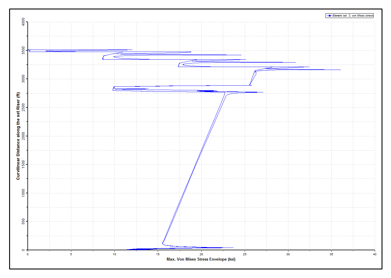
Maximum Von Mises Stress Envelope
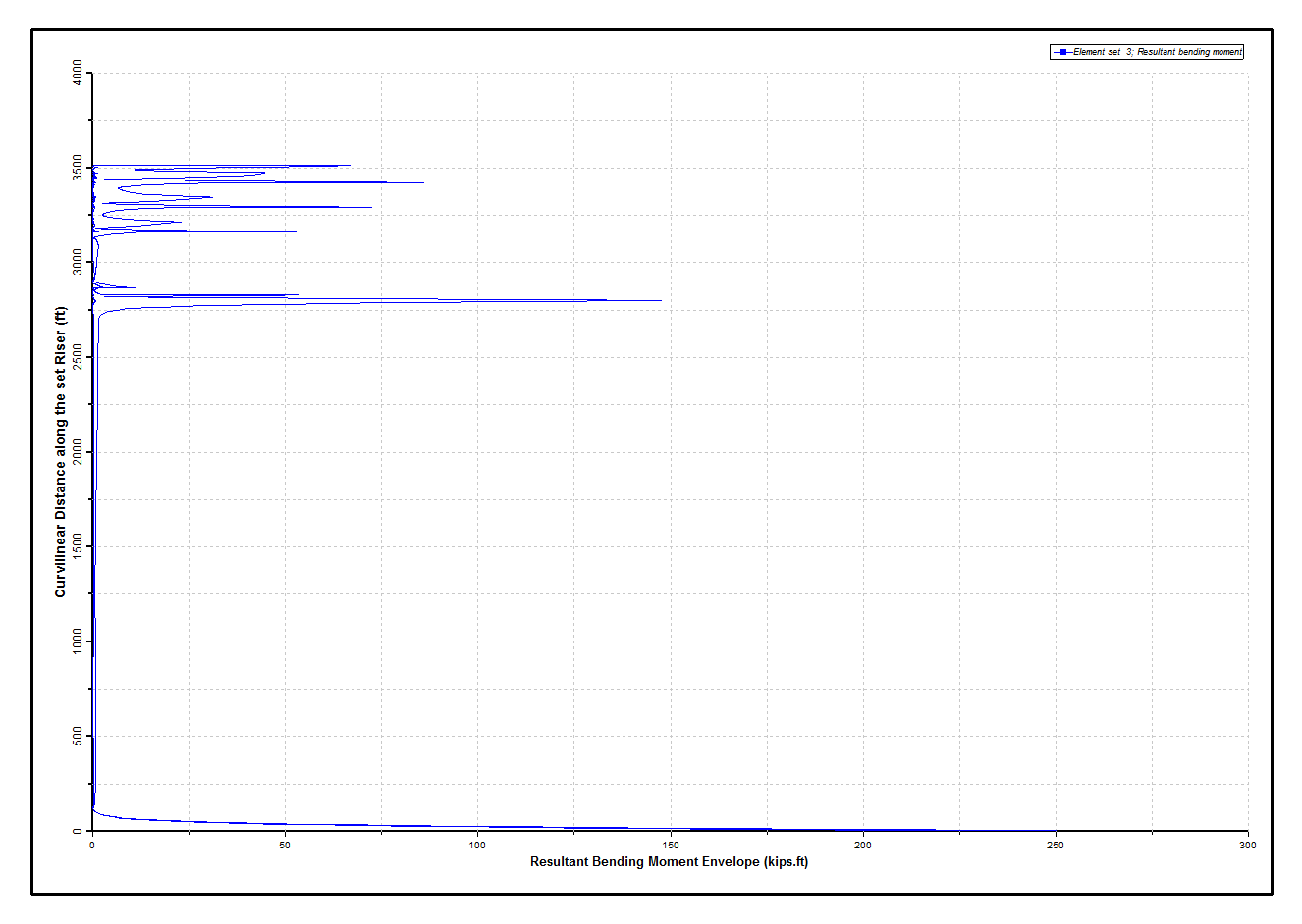
Resultant Bending Moment Envelope