Model Summary |
 
|
Model Summary |
|
In the simplified riser model used here, each of the three concentric sections is modelled using elements 25’ in length. This gives a total of 813 elements – in a more realistic model very many more elements would likely be used. In defining the nodal co-ordinates for the production tubing, the lowermost node (Node 1) is given an initial vertical co-ordinate 4’ above the packer level at -8000’, and is then moved to the packer by the application of a boundary condition. The 4’ is the amount by which the 12000’ of tubing will elongate under its own weight, and the definition of co-ordinates in this way ensures the tubing is slack at the packer. Likewise the lowermost node on the inner casing (Node 1001) has an initial vertical co-ordinate of 0.5’ above the mudline, and is again moved to the mudline via a boundary condition. This pre-stretch is to ensure acceptable base tension in the inner riser over its full working life.
The three sections are connected together by making the nodes at the top of each section equivalent. The nodes connected in this way are Node 485 on the tubing, Node 1165 on the inner riser, and Node 2165 on the outer. There is then a further single node above these for the application of the top tension of 1120 kips. Of course the lateral (horizontal) motions of the three sections are coupled by the pipe-in-pipe connections, which are applied at all nodes between the mudline and the three equivalent nodes at the Spar deck. As previously mentioned, these are of two types, linear and non-linear, which alternate over the full length from mudline to deck. The linear connections have a stiffness of 100,000 kips/ft. The non-linear are characterised by the force-deflection relationship shown below.
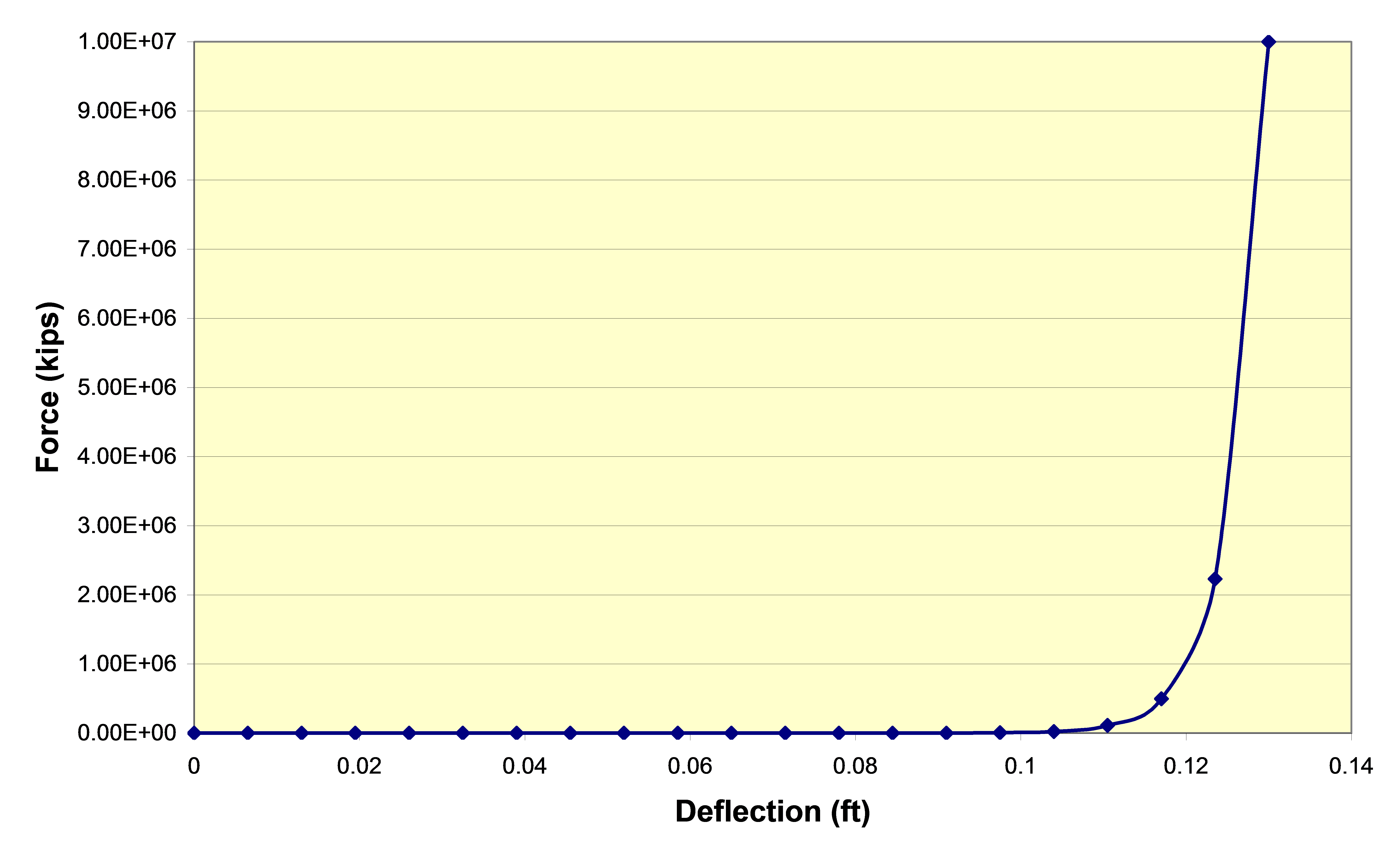
Nonlinear Connection Characteristic
In this specification, the force increases exponentially as the deflection approaches what is the same initial separation for both sets of sections, approximately 0.13 ft. The above plot is not necessarily intended to represent a physically reasonable specification; it is instead intended to show how a very simple contact model could be approximated. Note also that all the deflection values are positive – symmetry is assumed.
The model in the VIV portion of the example is similar to that discussed above, with two minor deviations:
•The tubing below the mudline is omitted, so the lowermost end is represented by Node 321 rather than Node 1.
•Node 321 is assigned an initial vertical co-ordinate of 1.333ft above its mean position on the mudline, which is subsequently adjusted via a boundary condition. This length is consistent with the approach discussed above, adjusted to account for the new length of tubing which is now 4000' rather than 12000'.