Drilling Riser Joints |
 
|
Drilling Riser Joints |
|
Four drilling riser joints are used to model the main body of the riser. Three correspond to the joints identified as Joints #1, #2 and #3 in the Riser Stack-Up Schematic figure, and a fourth “Termination Joint” models the 2 short pup pieces above these. The table below describes each of these joints in terms of outer diameter, wall thickness, joint length, and whether or not the joint has buoyancy modules attached.
Sample Element Lengths Riser Joint Data
Tubular |
Outer Diameter (in) |
Thickness (in) |
Length (ft) |
Buoyancy |
Riser Joint # 1 |
21 |
0.875 |
75 |
ü |
Riser Joint # 2 |
21 |
0.625 |
75 |
ü |
Riser Joint # 3 |
21 |
0.625 |
75 |
û |
Termination Joint |
21 |
0.875 |
45 |
û |
A number of peripheral lines surround the main tubular. These consist of a hydraulic line, two choke and kill lines, and a mud boost line. These peripherals are laid out as shown in the figure below. The 'Peripheral Line Data' table below gives outer and inner diameters for the various lines.
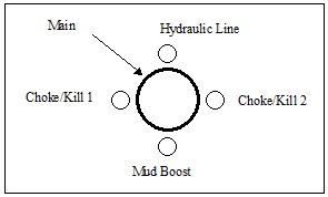
Peripheral Lines
Peripheral Line Data
Tubular |
Outer Diameter (in) |
Inner Diameter (in) |
Choke/Kill 1 |
5 |
3 |
Choke/Kill 2 |
5 |
3 |
Mud Boost Line |
4.5 |
3.75 |
Hydraulic Line |
3.5 |
3 |
The buoyancy modules attached to Joints # 1 and # 2 are described in the table below. This gives details of the buoyancy module dimensions, the number of modules per riser joint, and the so-called buoyancy material “densities”. Note that “density” in this context reflects common usage, but the values quoted are not strictly densities as rigorously defined in Flexcom. In Flexcom, density is always taken to mean mass per unit volume, whereas the “density” values in the table below represent instead weight per unit volume.
Outside Diameter |
Volume per Module (ft3) |
No. of Modules per Joint |
“Density” (lb/ft3) |
|
Joint # 1 |
Joint # 2 |
|||
47 |
48 |
10 |
26 |
31 |